Mastering the Wallfollowing Approach
An Exciting Start
Diving into the fascinating world of ROS (Robot Operating System), we venture into the concept of wallfollowing, with Lecture 3 laying the groundwork. It delves into the last ROS introductory topic—Rigid Body Transformation.
Imagine coordinate frames in ROS as being like radar stations, each providing specific, sensor-based information. These frames are essentially 3D grids with orthogonal X, Y, and Z axes, placed at a specific position. What’s thrilling is that these frames provide meaning to positions of objects, robots, and the like, but only when we establish the frame in which we’re narrating the pose.
How do we determine the direction of the axes, you might wonder? Well, it’s akin to shadow puppetry! The right-handed rule guides us - your index finger indicating the X direction, middle finger showing the Y direction, and the thumb pointing towards Z. Now, let’s delve deeper into transformations and frames!
Unraveling Transformations and Frames
Why are transformations between different sensors essential, you ask? Each time sensor data arrives, we aim to transmute it uniformly. For instance, consider the frame of reference of a lidar sensor, which we can morph into the robot’s frame of reference—located at the center of the rear axle. It’s similar to the previous assignment where we solely considered the lidar’s frame of reference to halt the car.
However, a car isn’t just a point in space—it has dimensions. The lidar sensor can be positioned in the center of the car, so correctly avoiding a collision should factor in the entire length of the car, not just the lidar’s position. Hence, a transformation that converts measurements from one frame to another exists between frames.
Navigating Reference Frames on F1Tenth car
map
Think of this as the user-defined origin. All transformations are measured concerning the map, which represents the car’s racing environment. Typically, once placed, it remains static.
base_link
Located at the center of the car’s rear axle, it moves relative to the map frame as the car progresses.
lidar
This frame captures where the lidar scan measurements occur, moving with the car relative to the map frame.
odom
A frame mandated by ROS, it usually represents the robot’s initial position on the map before the action begins. It’s fixed relative to the map.
The Dance of Rigid Body Transformation
To understand how to transform data and position between frames, let’s use the example of figuring out the coordinates of point p in frame 2, given its coordinates in frame 1.
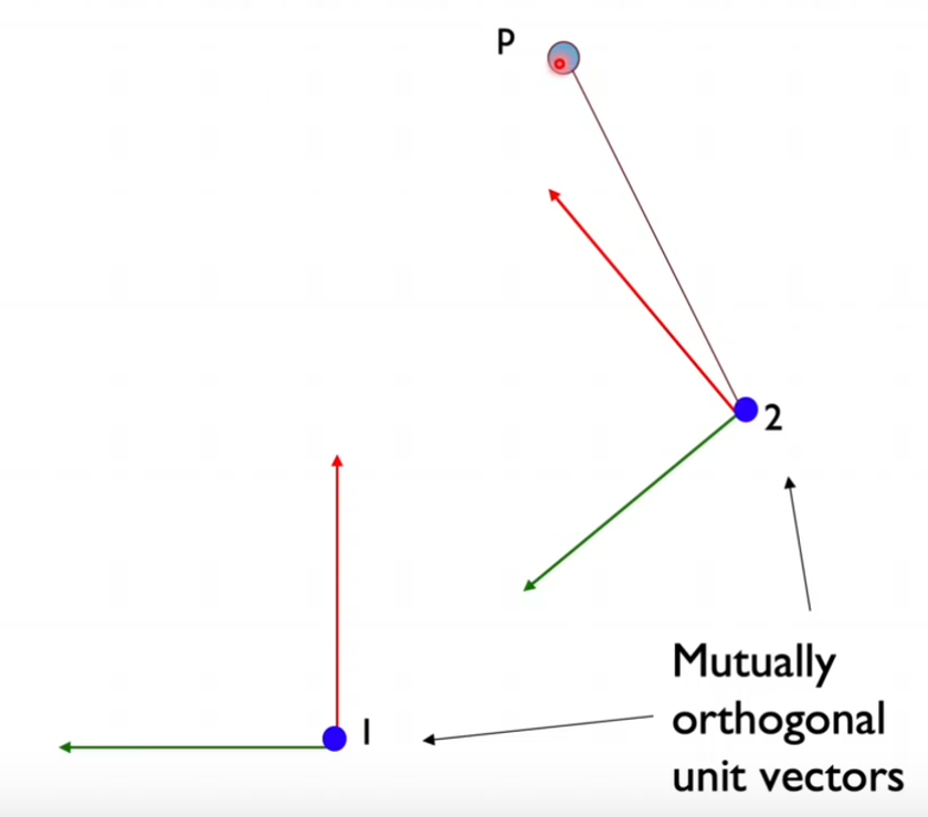
Image source: UV F1/10 course
How do we proceed?
- Overlap both frames so their origins converge. The rationale is to compute the rotation of the second frame of reference.
- Express the unit vectors of the second frame of reference in the unit vectors of the first frame of reference, as demonstrated in the picture below.
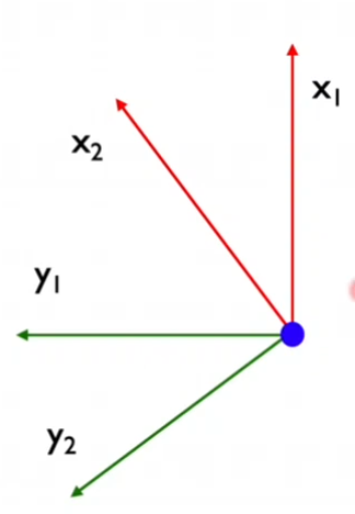
Image source: UV F1/10 course
Given:
x2 = R11x1 + R21 y1
y2 = R12x1 + R22 y1
We can see that the new frame of reference’s units vector can be represented as a linear combination of the original frame of reference (considering only X,Y axis - it’s a 2D problem, no Z). The formula can also be rewritten as a matrix:
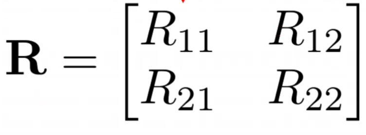
Image source: UV F1/10 course
In addition, we define θ as the angle between x1 and x2. This angle reveals how rotated this frame is.
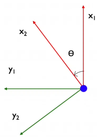
Image source: UV F1/10 course
To derive the coefficients R11, R21, R12, R22, we consider that along the x2 unit vector direction, there are cos and sin components of the x1 and y1 unit vectors respectively. Therefore, x2 and y2 can be written as:
x2 = cos(θ)x1 + sin(θ)y1
y2 = -sin(θ)x1 + cos(θ)y1
So, we get:
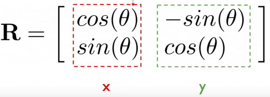
Image source: UV F1/10 course
With this matrix, we can represent unit vectors in the new frame of reference in terms of the original frame’s unit vectors. We can also express point P’s position in the new frame of reference using the rotation matrix, as shown below.
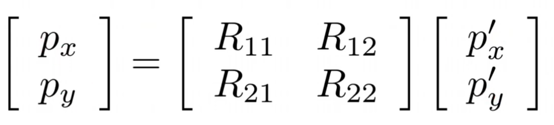
Image source: UV F1/10 course
However, don’t forget the translation too!
ROS tf/tf2 package
ROS tf2 package is a fantastic tool that lets you track multiple coordinate frames over time, enabling transformation between two coordinates. It broadcasts this across ROS, making it available to any subscribing node. To dig deeper, you might want to check out the TF2 Tutorial, the older TF Tutorial and TF2 Migration.
The Art of Wallfollowing
This technique revolves around computing the error between the future position of the car and the current error, considering the carThe video is of my car running the wallfollowing algorithm, this is my first lap of autonomously driving car.
That is it for this blog. I hope it was understandable enough. I really enjoyed this assignment, as always I learned a lot of new things. In the next blog I will move on to the waypoint following.